Hot and Cold Water Dispenser: How It Works
Hot and Cold Water Dispenser: How It Works
Introduction
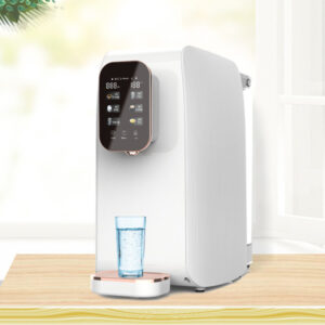
Water dispensers have become ubiquitous in modern households, offices, and public spaces, providing convenient access to both hot and cold water without the need for traditional boiling or refrigeration methods. A hot and cold water dispenser is an appliance designed to supply water at two distinct temperature ranges: chilled water typically between 4°C and 10°C and hot water between 85°C and 95°C. These devices are engineered to integrate seamlessly into daily life, offering energy efficiency, hygiene, and ease of use. Understanding how these dispensers function requires delving into their mechanical, electrical, and thermodynamic principles.
The evolution of water dispensers traces back to the early 20th century when bottled water delivery systems gained popularity. Today, they come in various forms, including countertop models, freestanding units, and point-of-use (POU) systems connected directly to a water supply. This article explores the intricate workings of a typical hot and cold water dispenser, focusing on its core components, cooling and heating mechanisms, dispensing processes, safety features, and maintenance requirements. By breaking down these elements, we can appreciate the blend of simple physics and advanced engineering that powers this everyday appliance.
At its heart, a hot and cold water dispenser operates on the principles of heat transfer, fluid dynamics, and electrical control systems. Water is sourced either from a replaceable bottle or a direct plumbing connection, then processed through separate pathways for heating and cooling. The dispenser’s efficiency hinges on insulation, sensors, and compressors that maintain desired temperatures while minimizing energy consumption. In the following sections, we will dissect these processes step by step, providing a technical overview suitable for engineers, technicians, and curious users alike.

Basic Components of a Hot and Cold Water Dispenser
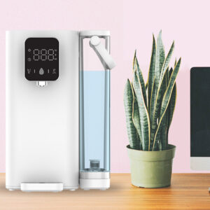
A standard hot and cold water dispenser comprises several key components that work in harmony to deliver temperature-controlled water. The primary structure includes a water reservoir or tank system, which is divided into hot and cold sections. For bottled models, a large plastic bottle (typically 5 gallons or 19 liters) is inverted onto the top of the dispenser, allowing gravity to feed water into the internal reservoirs. In POU models, water enters via a filtration system connected to the mains supply.
The cold water tank is usually made of stainless steel or food-grade plastic, insulated to prevent heat ingress. It holds a volume of water that is continuously cooled. Similarly, the hot water tank, often smaller in capacity, is designed with heating elements and insulation to retain heat. Both tanks are equipped with level sensors to detect water levels and prevent overflow or dry operation.
Electrical components play a crucial role. A power supply unit converts AC voltage to the required levels for operating compressors, heaters, and control boards. The control system, often a microcontroller-based circuit board, monitors temperatures via thermistors or thermocouples embedded in the tanks. These sensors provide feedback to regulate the heating and cooling cycles, ensuring consistent output.
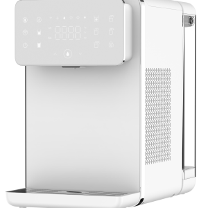
Additionally, the dispenser features dispensing valves or faucets, typically push-button or lever-operated, which control the flow of water from each tank. Drip trays collect any spillage, and UV lamps or ozone generators may be included in advanced models for sterilization. The outer casing, made of durable plastic or metal, houses these internals while providing aesthetic appeal and user interface elements like LED indicators for temperature status.
Understanding these components is essential as they form the foundation for the dispenser’s operation. For instance, the insulation materials, such as polyurethane foam, reduce thermal conductivity, allowing the system to maintain temperatures with minimal energy input. This design not only enhances efficiency but also complies with energy standards like those from ENERGY STAR.
The Cooling Mechanism: Refrigeration Principles at Work
The cooling system in a hot and cold water dispenser relies on vapor-compression refrigeration, a thermodynamic cycle widely used in refrigerators and air conditioners. This process involves four main stages: compression, condensation, expansion, and evaporation, facilitated by a refrigerant gas such as R-134a or more eco-friendly alternatives like R-600a.
At the core is the compressor, an electric motor-driven pump that compresses the refrigerant vapor, increasing its pressure and temperature. This high-pressure gas then flows to the condenser, a coil of tubing located at the back or bottom of the dispenser. Here, heat is dissipated to the ambient air through natural convection or forced by a fan, causing the refrigerant to condense into a liquid state.
The liquid refrigerant passes through an expansion valve or capillary tube, where it undergoes a sudden pressure drop, leading to partial evaporation and a significant temperature decrease. This cold mixture enters the evaporator coils, which are wrapped around or immersed in the cold water tank. As the refrigerant evaporates fully, it absorbs heat from the surrounding water, cooling it down. The vapor returns to the compressor, completing the cycle.
Thermostatic control ensures the cooling operates only when necessary. A thermostat sensor in the cold tank signals the compressor to activate when the water temperature rises above a setpoint, typically 10°C, and deactivates once it reaches 4°C. This on-off cycling, known as bang-bang control, optimizes energy use but can lead to minor temperature fluctuations.
In terms of efficiency, the coefficient of performance (COP) for these systems is around 2-3, meaning for every unit of electrical energy input, 2-3 units of heat are removed from the water. Factors like ambient temperature, insulation quality, and refrigerant charge affect this. Advanced models incorporate variable-speed compressors for smoother operation and better energy savings.
Potential issues in the cooling system include refrigerant leaks, which reduce cooling capacity, or compressor failures due to overheating. Regular maintenance, such as cleaning condenser coils to remove dust, is vital to prevent efficiency losses. By understanding this refrigeration cycle, users can troubleshoot common problems like insufficient cooling, often traced to blocked airflow or low refrigerant levels.
The Heating Mechanism: Electrical Resistance and Thermal Control
Contrasting the cooling side, the heating mechanism employs straightforward electrical resistance heating to raise water temperature. The hot water tank contains one or more immersion heaters, typically rated between 500W and 1500W, made of nichrome wire coiled within a protective sheath. When electricity flows through the wire, resistance generates heat via Joule’s law (P = I²R), where P is power, I is current, and R is resistance.
Water enters the hot tank from the main reservoir or supply line, filling it to a predetermined level controlled by a float valve or solenoid. The heater activates, rapidly bringing the water to the desired temperature. Insulation around the tank minimizes heat loss, and a thermostat maintains the temperature by cycling the heater on and off.
Safety is paramount in heating systems. Overheating can lead to scalding or tank rupture, so dispensers include bi-metallic thermostats or thermal cut-offs that interrupt power if temperatures exceed safe limits, around 100°C. Some models use positive temperature coefficient (PTC) heaters, which self-regulate by increasing resistance at higher temperatures, preventing overheating.
Energy consumption for heating is calculated based on the specific heat capacity of water (4.184 J/g°C). To heat 1 liter of water from 20°C to 90°C requires approximately 292 kJ, or about 0.081 kWh at 100% efficiency, though real-world figures are higher due to losses. Standby modes keep the water hot with intermittent heating, consuming 0.5-1 kWh per day.
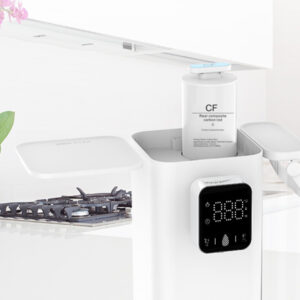
Integration with the overall system ensures no cross-contamination between hot and cold paths. Separate tubing and valves prevent thermal mixing, maintaining distinct temperatures. In POU systems, incoming water may pass through filters like activated carbon or reverse osmosis membranes before entering the tanks, removing impurities and improving taste.
The Dispensing System: Fluid Dynamics and User Interface
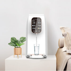
Dispensing water involves fluid dynamics principles to ensure smooth, controlled flow. When a user activates the cold or hot faucet, a valve opens, allowing gravity or pressure to propel water through dedicated spouts. In bottled models, atmospheric pressure equalizes via a vent tube, preventing vacuum lock.
Flow rates are typically 1-2 liters per minute, governed by nozzle diameter and tank head pressure. Solenoid valves in advanced units provide electronic control, enabling features like measured dispensing for cups or bottles. Child-lock mechanisms on hot faucets use spring-loaded levers to prevent accidental activation.
The user interface often includes indicator lights for power, heating/cooling status, and low water alerts. Touch-sensitive panels or buttons interface with the control board, which processes inputs and manages outputs via relays.
Hygiene is maintained through antimicrobial coatings on spouts and UV sterilization in the tanks, reducing bacterial growth. Drip trays with grates allow easy cleaning, and some models feature self-draining systems.
Safety Features and Regulatory Compliance
Safety engineering in water dispensers addresses electrical, thermal, and biological hazards. Ground fault circuit interrupters (GFCIs) protect against shocks, while insulated wiring prevents short circuits. Thermal fuses and pressure relief valves safeguard the hot tank.
Compliance with standards like UL (Underwriters Laboratories) or NSF (National Sanitation Foundation) ensures materials are non-toxic and systems are leak-proof. Energy efficiency ratings guide consumers on operational costs.
Maintenance and Troubleshooting
Regular maintenance extends dispenser life. Cleaning tanks quarterly with vinegar solutions removes scale, while replacing filters prevents clogs. Troubleshooting involves checking power supplies for no-operation issues, inspecting coils for cooling failures, or testing heaters for heating problems.
Common faults include thermostat drift, leading to incorrect temperatures, or valve leaks causing drips. Professional servicing is recommended for refrigerant issues.

Conclusion
Hot and cold water dispensers exemplify efficient thermal management in consumer appliances. By integrating refrigeration, heating, and control systems, they provide reliable access to temperature-controlled water. As technology advances, expect smarter features like IoT connectivity for remote monitoring. Understanding these mechanisms empowers users to optimize usage and maintain their devices effectively.
For more info about hot and cold water dispenser how it works, you can pay a visit to Olansi at https://www.olansgz.com/how-does-a-reverse-osmosis-hot-and-cold-water-dispenser-work/ for more info.